Day 3: Finishing Up

We started today of by arranging the LEDs by assigning them individual numbers 1 to 11 as we’re using 11 LEDs per arduino, and splitting them up into 4 sections. The Diagram shows that each LED is wired up to a certain arduino in the section, the arduino being the box in the middle of each section.

Day 3 Organizing

We are planning on using 4 arduinos, 1 master and 3 slaves so we can power all LEDs without loosing the individual control of each one. We can also only control 13 LEDs max per arduino but as we’re using 3 slaves we need to leave 2 slots free. Below is an image showing some of the code behind the 4 arduinos.

Day 3 Master/Slave Day 3 Master/Slave 2

Once all the arduinos had the code uploaded onto them, we began putting all the LED wires into the correct socket.

Day 3 Wiring Up

Once we had all the LEDs wired up we tested, we sorted the ones that weren’t working and started soldering the sensors into place and got them connected up.

Day 3 lights Day 3 nearly there

Once we completed the coding for each arduino and fixed all the wiring niggles we tested the board out. Here is a video of the result:

Day 2: Installing LEDs

Once we managed to solder 11 LEDs, we decided to hook them up to an arduino and test to see if the LEDs worked and to double check if we had enough power to power all 11 LEDs of one arduino. The first photo shows all the wires connected running of a battery, this was just a test and wont look this messy.

Day 2 LEDs connected


Once we put the LEDs in the correct holes this was the result we got, the 2 middle ones wasn’t working that was due to the soldering.


Day 2 All LEDs 2 Day 2 Example Day 2 Example 2


While 3 of us were testing the LEDs, we had 1 person testing and configuring the sensors to detecting movement.

Day 2 Sensors


By the end of the day we had all 44 LEDs soldered up and placed into the correct holes. Before we put them through the holes we had to test all LEDs just to double check they were working before going ahead and positioning them.

Day 2 All LEDs

Day 1: Starting the build

the first thing we had to plan out was where we were going to place the LEDs, as you can see in the photo below we penciled out the lines to double check the LEDs were equally spaced out and had enough space to fit the wooden frame around the cardboard backing.

Day 1 build


Once we got the frame to fit the cardboard backing, we cut of the excess cardboard and began wrapping the the top with tin foil.

Day 1 Tin FoilDay 1 Tin Foil 2

Once we had wrapped all of the top with tin foil we began punching the LEDs holes through and stuck the frame to the cardboard using wood glue, we also included the extra bit of frame to raise the foam up once we attach it.

Day 1 Wood FrameDay 1 Wood Frame 2


Sourcing the parts

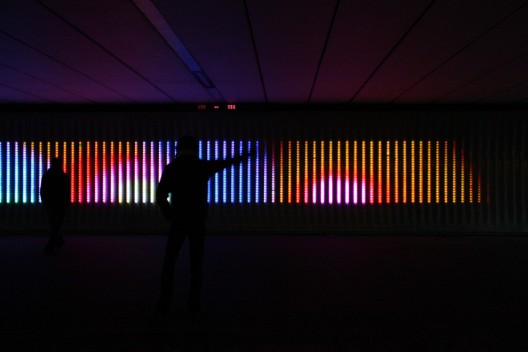
In order to complete our goal of an LED wall that interacts with people we require a large amount of kit.

First off to control the LEDs we need 4 arduinos as each only has 13 digital pins, 11 of which we will be using, giving us 44 individually controllable outputs. We have managed to collect 4 now through our own ones and ones borrowed from the university.

Next were the LEDs, we looked at using over 500 LEDs and then quickly released how much this project will become,we worked out that we would need over 100m of wire which would come to at least £50 and this wasn’t including the LEDS and solder. We decided to make it smaller and only use 50 LEDs max we decided to buy these from ebay to keep the price down however, although we paid for first class delivery they did not arrive on time and do have delayed the progression of our project putting us on the backfoot a bit and against time, for each LED we also bought a 220 ohm resistor which was around £5. While we were looking at LEDs, we checked out at using sensors to detect movement, we managed to 3 for £25.

Next we needed to get some wood for the frame of the whole project which was just under £10, we decided to not use wood as the base as we bumped into a few problems one of them being we didn’t have the correct tools and Brunel labs were having a few technical problems, we decided to use cardboard which we got free at a hardware store. While we were at the hardware store we brought some foam to put over the LEDs which will help the LEDs look brighter and cover a larger surface the cheapest we could find was 15 square meters priced at £12.

The most important thing we needed was wire to connect all the LEDs and basically everything together, at first we over judged how much wire we needed like I mentioned above, after rearranging the arduinos we managed to judge that we needed 20m, but brought 28m just in case. This time we under judged and ended up getting a less than we need, in the end we ended up getting 48m which came to around £24.

The last few bits we needed were batteries, tin foil and the tools. The main reason behind the tin foil is to help the LEDs look bright, if we just left the cardboard it wouldn’t reflect of, with the tin foil it would reflect of making it look a lot brighter.

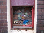
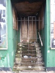
Here are some of the parts and tools which we have listed and described above.

Day 1 Parts


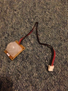
These are the sensors we purchased online and have decided to use for motion detection.

Sensor

The science of pedestrian movement and our final idea

According to a paper by Willis et al. (2003) entitled Human Movement Behaviour in Urban Spaces: Implications for the Design and Modelling of Effective Pedestrian Environments, ‘Predicting individuals’ movement patterns through space is becoming an increasingly important goal of urban and transport planners interested in designing effective urban spaces for pedestrians’.

To this end, bearing in mind the Archaeology department at Plymouth University and ArchOS mentioned previously we came up with our final idea.

We have decided to create an interactive LED wall which senses pedestrian movement, uploading the data live to Cosm while also giving people an artwork to interact with giving the feeling of being connected with the architecture around them.

Rethinking our project

We took some time over the past few days to have a think about our project and what we might like to change. As a group we were interested in the ArchOS system developed collaboratively between the Archaeology and Digital Art and Technology departments at Plymouth University and were interested in creating something of a similar nature combining technology and environmental sensors with the city.

ArchOS was developed for the build of Portland Square, one of Plymouth University’s buildings. It uses sensors attached to the building to measure wind speed, temperature and so on. As our module project is described in a nutshell as an Urban API, which translates to me as an interaction between people and the city, we thought of using a similar system but sensing people’s behaviour as opposed to environmental variables.

To this end we settled on movement of pedestrians. We are interested to find how pedestrians move through the city of Plymouth, where they go and when. This satisfies half of the brief, the portion which is looking for data from the city, however we are yet to think of a way to make this interactive.

Exit from the Stonehouse Group project

Having thought long and hard about this we sadly as a group decided that we wouldn’t be pursuing our project alongside the Stonehouse Group’s Union Street Community Gallery. There are a few reasons to this, one being that we felt our project didn’t quite fit the idea of the Community Gallery.

This does mean however that we may possibly be rethinking our completely redeveloping our idea for this project for our final deadline.

Not much thought on that at the moment but keep checking back for more.

Site Images – Union Street

We took a trip to Union Street the other day to get a feel for the area we’re going to be analysing and hopefully exhibiting our work on. We wanted to take a close look at the Palace Theatre as it will most likely be the main subject of our project. Below are some pictures we took of the area.